Used ICs: A4598 – UPD6376CX – HD6433298A 16P – MN4464-08L-1 – HG52E35P – HG51B155FD – BA612 – LB-603VP1(Display)
Number of keys: 61
Polyphony: 32-note(max.)
Preset tones: 128
Magical preset: BREAK BEAT 16 MELODYCOMP 8
SHADOW DRUM 4 FREE SESSION 32
TONE STACK 40 KEY SPLIT 12
HYPERACTIVE 16
Auto-accompaniment: Rhythm patterns 128
Tempo Adjustable(40 - 255)
Chords Three system: CASIO CHORD, FINGERD,
FULL-RANGE CHORD
Other Variation pattern, fill-in pattern, intro/ending pattern for each rhythm.
Song memory: song:one
System:Real-time recording
Memory capacity:Up to 1,300 notes
Registration memory: 4 setups
Sound control pads: Phrases 10
Drums 10
SE/Percussion 10
Controller 2
Digital effects: REVERB 1, REVERB 2, REVERB 3, CHORUS, TREMOLO, PHASE SHIFTER, ORGAN SP, ENHANCER, FLANGER, EQLOUNDNESS
DEMO tunes: 3 tunes
Other functions: Transpose (F# ~ C ~ F : half-note)
Tuning adjustable A4 = 440KHz 50 cents increments
Volume control (Main /Accompaniment)
Speakers: 12cm diameter X 2 (Output:2W+2W)
I/O terminals: Power supply 9V DC jack
Headphones Stereo mini jack
Output impedance:100 ohm
Output voltage:4.5V(RMS. max)
Assignable jack Standard jack
MIDI IN, OUT
Power supply: 3-way AC/DC power sources;
Batteries Six D-size
Battery life Approximately 5 hours on R20P(SUM-1)
AC Required optional AD-5 AC adaptor
Car battery Required optional CA-5 car adaptor
Auto power off: Approximately 6 minutes after the last operation
Power consumption: 7.7W
Dimensions: 942 X 367 X 135 mm(HWD)
31 7/16" X 14 1/2" X 4 3/8" inches(HWD)
Weight: 5.2kg(11.7lbs) excluding batteries
Accessory: Score stand
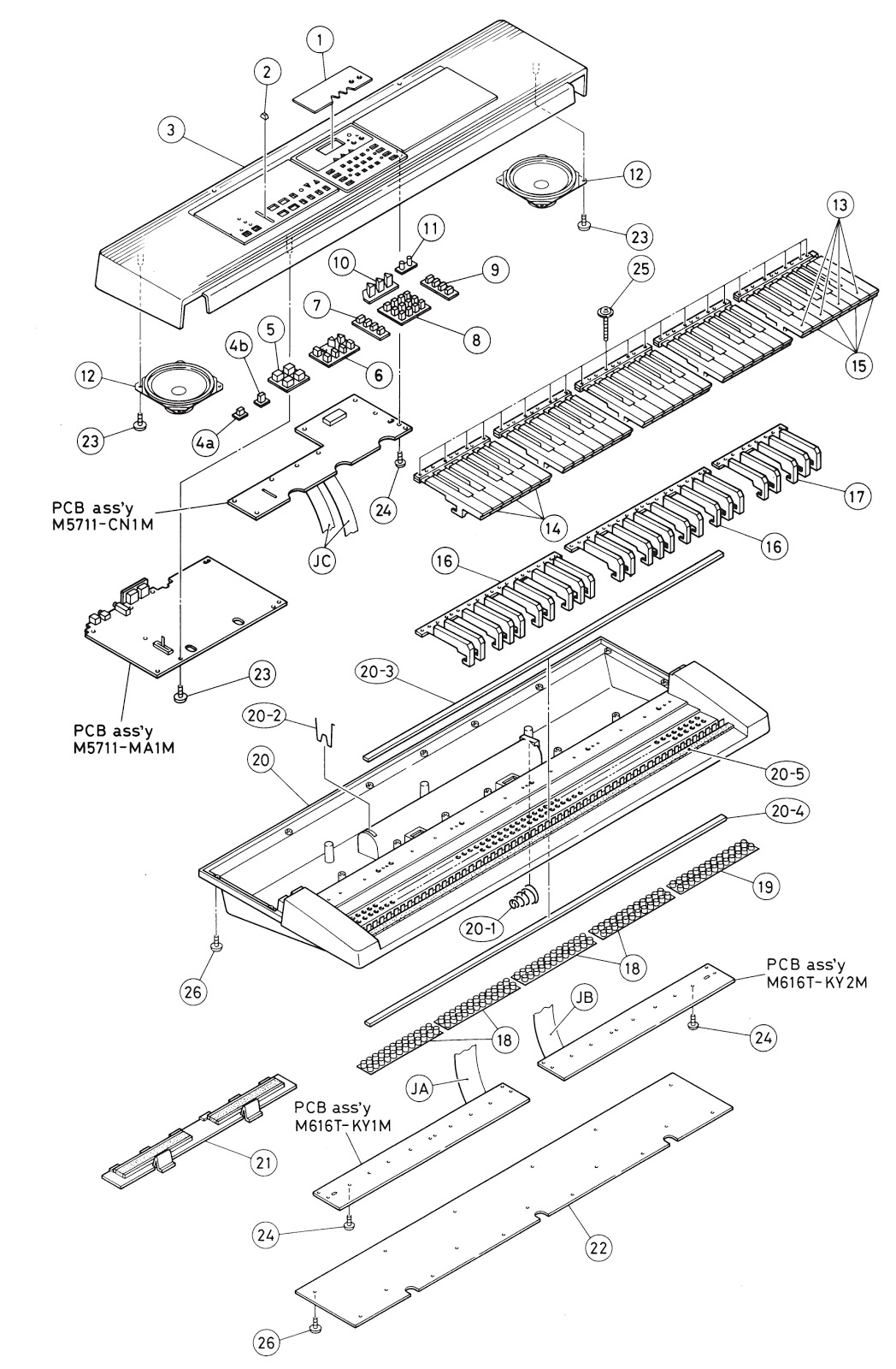
Exploded view [Click on the pictures to magnify]
Circuit diagram


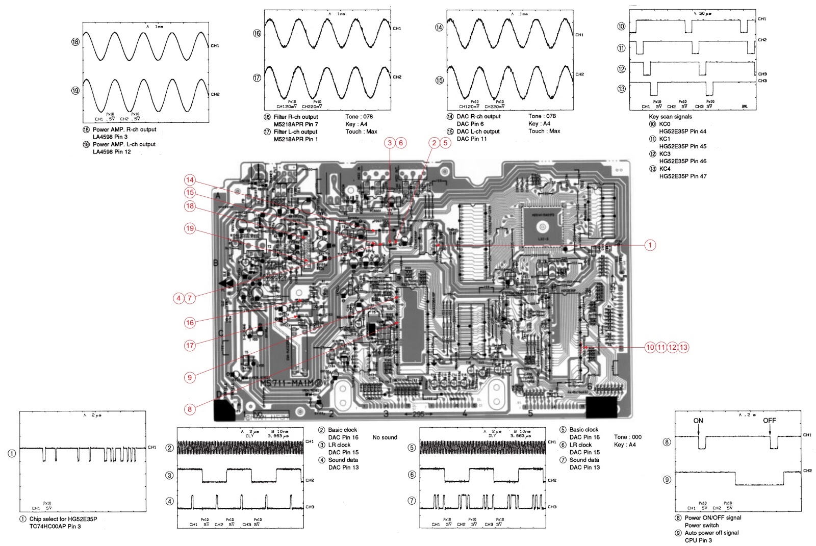


Circuit details


